
DUAL OSCILLATOR MODEL 258

258 Panel artwork, photo credit to Switched On
If there ever was an oscillator you heard more frequently than not in Buchla recordings, this is it. The Dual Oscillator Model 258 is an oscillator that most people try to emulate or obtain through clones or other means.
The heart of a 258 is a triangle core oscillator with a very straightforward and clear design. Top section is sawtooth, bottom section is squarewave, although these shapes are derived from the same modified sine wave (which is shaped from a triangle). Lots of waveforms being modified here. However, this is not a true waveshaper, it merely is a specialized crossfading mixer that scrubs a mix between the two waveforms.
Don wanted the oscillators he designed to maintain the properties of acoustic instruments. Because of this, the shape of many of these waveforms are not pure mathematical representations, they are full of quirks and anomalies. One could take a step further and say they have “mojo”. One thing is certain: the Buchla oscillator is a unique and beautiful snowflake.

258 documentation from the Buchla 200 Series Catalogue
258 VERSIONS
The 258 comes in 4 different flavors. Some of these designs utilize changes that revolve around the linearity of the FM behavior.
258
This 258 is extremely rare. The number of these made are in the single digits. The original 258 was the oscillator included in the Electronic Music System #3, included in the same system as the 410 Module Cluster. According to the schematic, the 258 for CBS dates back to March of 1970.
It is a much simpler design, and the board is slightly shorter than the later revisions.
This specific 258 belongs to Tom Rowlands of The Chemical Brothers.

258A
The 258A fixes a few bugs on the original 258. The 258A was also designed for CBS, and was a result of constant modification to the first revision of the circuit. The 258A first makes an appearance in a redrawn schematic dated in June of 1970, a mere three months after the first module was made for the Electronic Music System #3. The LM307 ICs were changed to a more stable ua741, namely, and many resistor adjustments were made to the circuit. Larger trimmers were added with through board adjustment for easier tuning after manufacture. The 258A has exponential FM modulation.
This module belongs to Chris Whitten, and is part of his Electronic Music System #3. It is entirely possible that his module was swapped out for the 258A due to issues with the original module.

258B
The 258B is a perplexing version of the 258 - there is not much out there in the wild in terms of a 258B PCB, but careful consideration must be taken when inspecting a 258A or even C to discern if the 258 is a “modified B”. On the component placement sheets, the 258B pcb layout is the same as the 258C, but the C implements component additions and changes. We found that at University of Illinois, their 258A was actually a B, as it carried all of the B modifications.
It’s important to note that there are 258As out in the wild that have redacted parts and changes that are not quite 258Bs. These are intermediary modified modules that were changed in April of 1971. It wasn’t until September of 1973 when the module became a B, to fix issues with the high frequency linearity.

Changes on the 258A schematic to dictate when the revision changes.
The photo to the right is the 258B from University of Illinois, which is the only 258B we have ever come across.

258C
The 258C is the version of the oscillator with linear FM response. The oscillator of choice for compositions that rely on more melodic content, as more extreme FM modulations can render tuning useless.
The C revision came almost immediately after the B, in the same month. It would seem that Don was refining this oscillator so frequently that the revisions would overlap.
Sometimes we come across photos that are low quality, and that is all we have to work with. This image comes from a very old camera, taken by Paul Schreiber of Synthesis Technology.
Note that the tantalum caps in the top left and right of the image are 4.7uF. This is an indicator that this C is indeed a C, because the B circuit can take up residence on this board. If it was a B, it would be 15uF. There are many other changes but its the easiest way to spot it right away.

258 REPLICATION
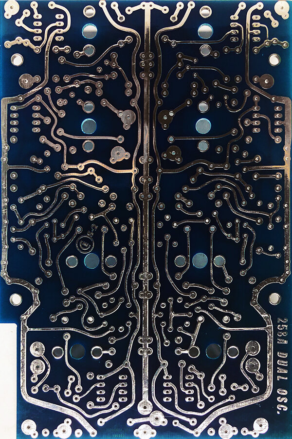
The 258A you see here has been documented with help again from the incredibly talented (and all around nice guy) Chris Whitten in the UK. This is also one of the many double sided boards that were deciphered over many hours of cross checking and teamwork.
All four of these oscillators have been built and tested by us. Our addition to the ecosystem is a legitimate 258B board, without kluges.

258A, Original PCB
M.E.M.S. Tracing result and new PCB

EAGLE detail, every DRC disaster known to man