
DODECAMODULE MODEL 212

212 Panel - Photo from MEMS - Oberlin Conservatory

Photo courtesy of SwitchedOn
The 212 Dodecamodule is a one stop shop for 200 series modifiers and utilities. It was originally included in the System 101, outlined by the catalogue page below. When paired with a 258 Dual Oscillator and 237 Keyboard, a versatile system takes shape. Two oscillators with enough utility to create quite the impressive Buchla experience, all distilled to one small compact unit. One could say that the System 101 was the bridge between the Electronic Music System #3 and the Music Easel, each iteration packed more and more of Don’s vision into a portable package.
The name of the Dodecamodule comes from the Ancient Greek “dodeca”, meaning “twelve”. It is significant to the number of separate sections of the module. Also attached from the November 1971 Buchla & Associates catalogue for the Series 200, a list price and some additional descriptions of the 12 functions.


212 documentation from the Buchla 200 Series Catalogue

OBERLIN’S DODECA


Component side placement guides for the 212 - Courtesy of David Kean

2 layer stackup of the placement guide and photo of the Oberlin PCB.
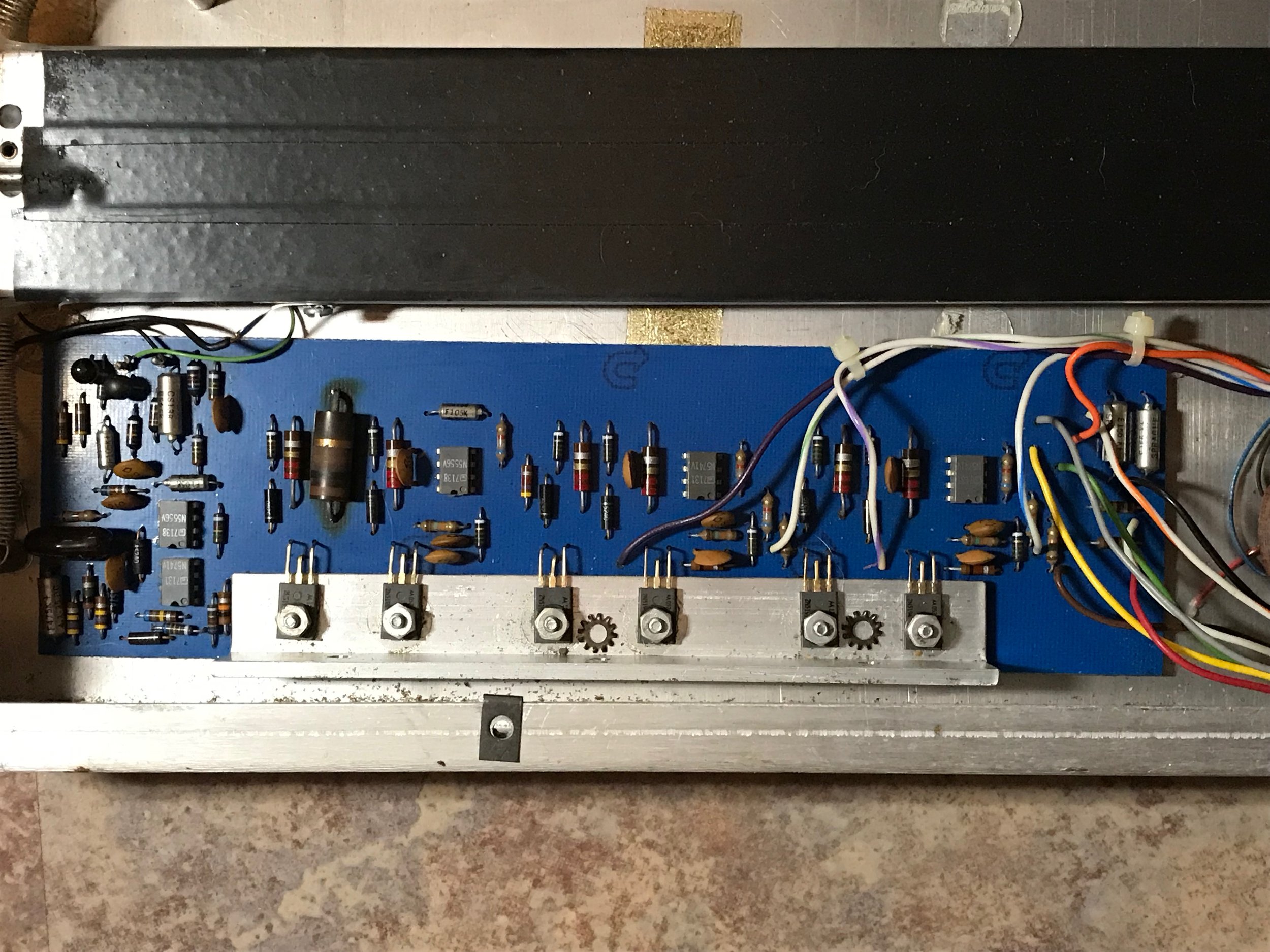
The Dodecamodule at Oberlin Conservatory of Music is where we first gained access under the hood. Each section of the Dodecamodule is clearly labeled on the PCB, for easy servicing. This is similar to the labels on the PCB for the 410 Module Cluster. Oberlin had a large document library on the system in their archives, including scans of reverse engineered Dodecamodule sections, so the Conservatory could keep a service record of the instrument.
These scans were sent to us by Tom Lopez, the Director of TIMARA at the time. It is intriguing to see that no matter the era, there was curiosity in replicating and studying the schematics to these modules. It’s worth noting that a lot of this replication was fueled by Don’s desire to push forward. Universities like Columbia in NYC had made attempts to order more 100 Series modules multiple times, but Don had moved on - which caused the University to reverse engineer and build their own clones.
NOISE SOURCE

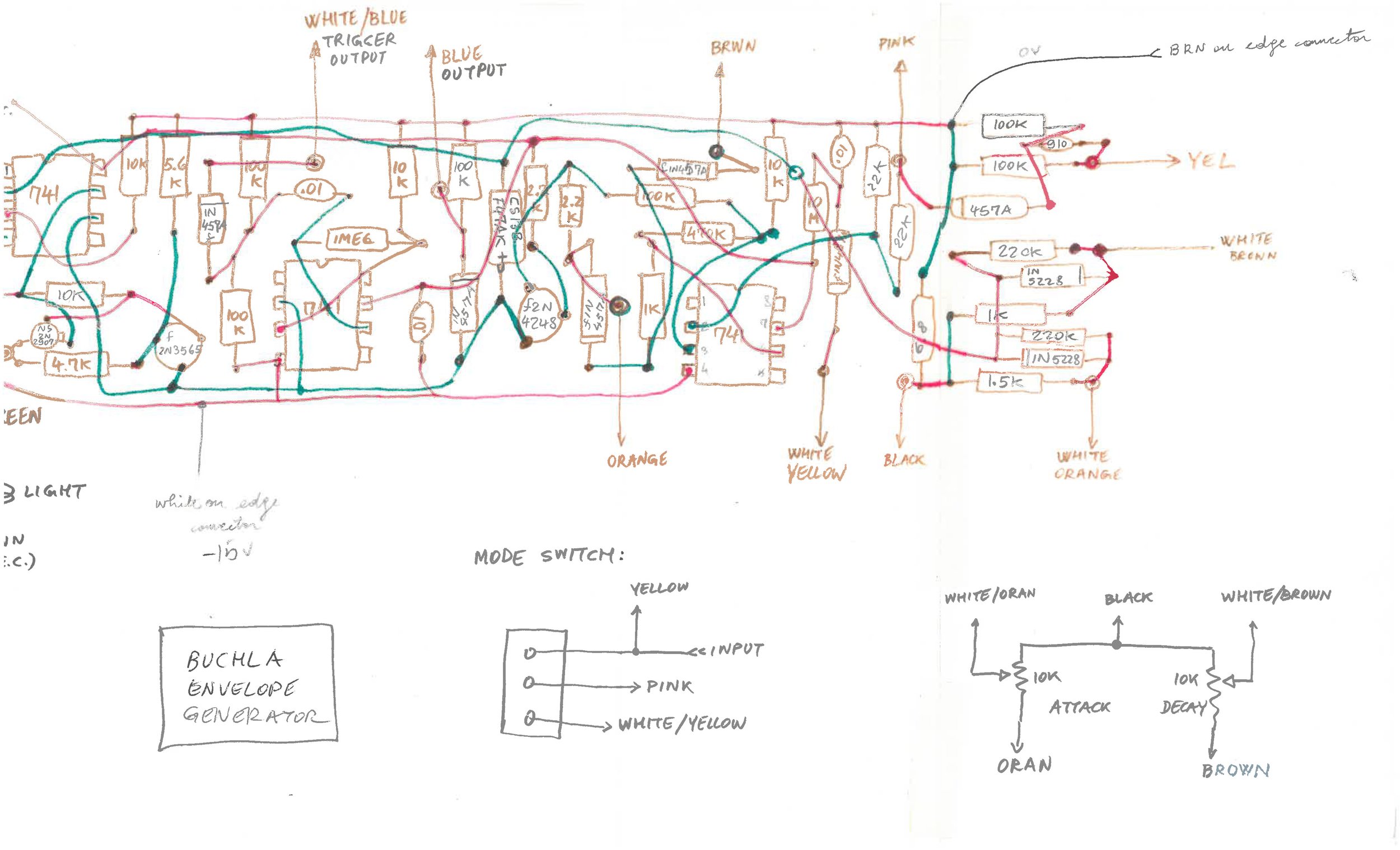
ENVELOPE GENERATOR

ENVELOPE DETECTOR


REVERB
The reverb driver is mounted in the bottom of the Dodecamodule’s boat. As you can tell, it pulls a decent amount of current, that high wattage resistor gets quite warm.
212 REPLICATION
This was a massive undertaking. We did not have a full schematic at the time of reverse engineering, so we used what scans we had from Oberlin, along with standard 200 Series schematics. Many of these circuits were reverse engineered visually, and the hours added up. The final replica also mounted the reverb driver and recovery board onto the back of the module, with an aluminum plate for shielding.
