
WAVEFORM SYNTHESIZER MODEL 132
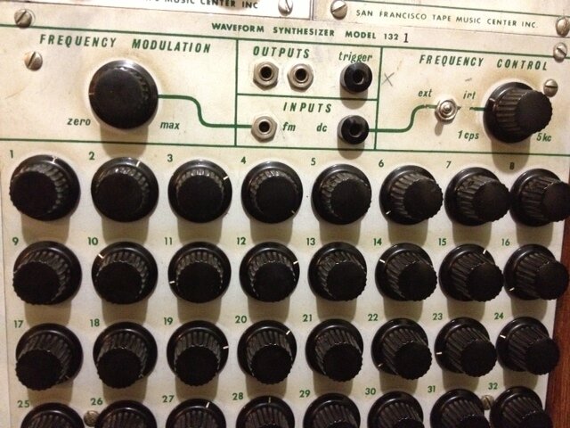
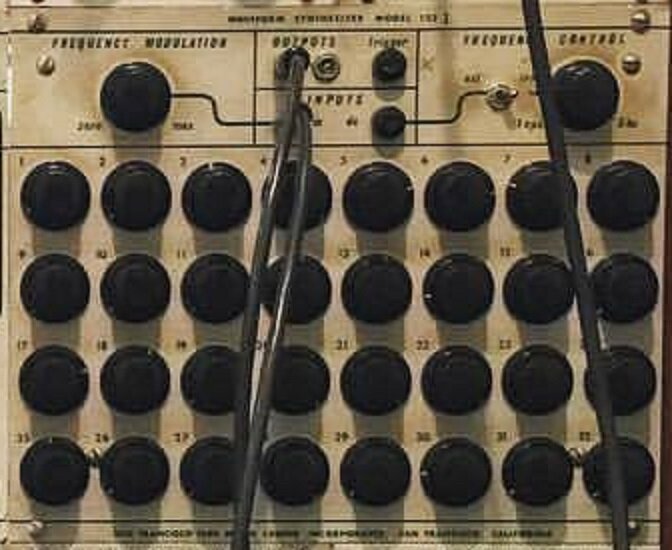
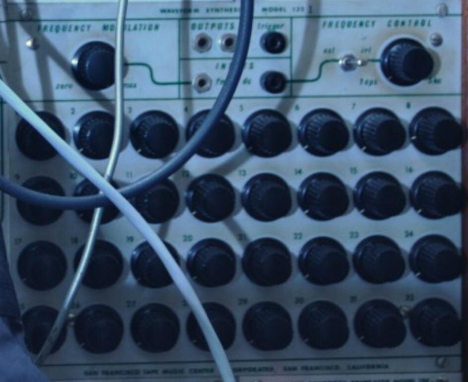
Before we talk about the 132, kindly refer to the set of photos on this page, the first ones you see. These were images of the 132 that were found online, and they do not win any blue ribbons for quantity or quality categories. Since we first saw images of the Mills system, the Waveform Synthesizer quickly landed in first place for the Buchla Hen’s Tooth category.
Since the data collection and grueling prototyping of the 132 is considered a crowning achievement of M.E.M.S. research, this will be a long-form page with some Hunter S. Thompson-esque vibes. It’s time to inject ourselves into the story and exercise a little bit of Gonzo research.
WHAT IS THE WAVEFORM SYNTHESIZER?

This single picture sums up this entire page. The project’s secondary objective is to inundate Chip with information and try to distract him at any cost.
A simple question, with a very complicated answer. You could simply say that it was an audio rate sequencer, running at an extremely high speed. You wouldn’t be incorrect in coming to this conclusion. But, the 132 is much more under the hood. You could also come to the conclusion that it sounds awful. But that would be paraphrasing. Don’t parrot what you read online. Let’s go back to a more rudimentary question.
WHAT IS A WAVEFORM?
We won’t really run you through the whole sine/saw/square/triangle fiasco. If you’re here, you know what a waveform is. What I want you to think about is the DEFINITION of a waveform.
According to Electronics, 2nd ed. (David Crecraft, David Gorham):
“In electronics, acoustics, and related fields, the waveform of a signal is the shape of its graph as a function of time, independent of its time and magnitude scales and of any displacement in time.”
Focus on the concept of TIME here, because if you think about the 132 in terms of a string of “incidents”, rather than a resulting waveform, it is much easier to digest the controls. Don was designing the 132 around the concept of moving voltage through the temporal realm at such a speed that it becomes a continuous waveform. Because the frequency knob dictates cycling rate of a manually set waveform, it is very easy to get lost when tuning it, as the output frequency may not always line up with the frequency knob’s position. A little more on that later.
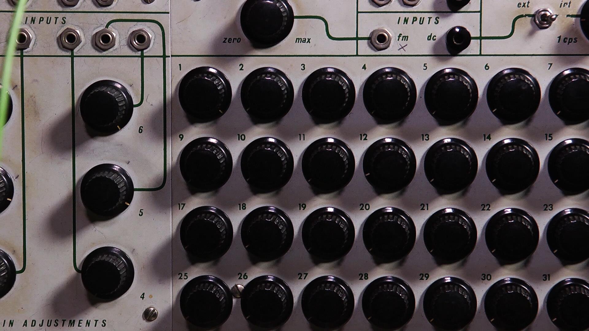
A simple and elegant explanation of the 132 comes from Chip Flynn, who called it a “voltage Etch-a-Sketch”. The 32 knobs adjust amplitude of each step to form a string of 32 partials. The sequence is swept at an extremely high frequency; the pulser circuit that forms the core of the 132 is running at a range of 32cps to approximately 160kc which sets the cycling frequency of each 32 step sequence at 1cps to 5kc.
WAVEFORM RESOLUTION
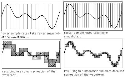
Resolution can severely impact the way we hear the same waveforms.
The main caveat with any graphic oscillator is RESOLUTION. Think of this as if it were sample rate. The more snapshots of the waveform (steps to the sequence), the smoother the waveform sounds to our ears. To avoid using up an incredible amount of panel space, Don probably decided on the 32 steps as a reasonable trade off when considering how difficult it is to patch already. Otherwise he could have made a 64 or 128 step sequence to facilitate a smoother waveform.
Without any circuitry to round off the corners of each step, the 132 sounds strangely digital for something made around 1965. This becomes incredibly apparent when drawing standard waveforms, like sawtooth, sine, or triangle. One could say that the strong point of the Waveform Synthesizer is not recreating waveforms, but exploring new ones. The problems with resolution also diminish at higher frequencies, as it becomes less discernible once we lose track of the steps at these speeds.

A sinewave broken up into 32 partials. Note the stepped amplitudes, almost like a 16 bit representation of an analog signal.
FREQUENCY: CYCLE OR SEQUENCE?
One of the first things we noticed about the 132 is the unique frequency range. 1 cps to 5 kc is quite a broad range, covering subsonic and supersonic frequencies that weren’t normally used in composition. Then the realization hit us; the frequency knob does not dictate the pitch of the oscillator directly.
What? It may not make sense at first, but think of it this way:
Imagine turning all 32 knobs to zero, and then turning all of the odd numbered knobs fully clockwise. Set the frequency to 1 cps and hook it up to a frequency counter. We would have a reading of 16 cps. Now turn everything except 1, 9, 17, and 25 to zero. Now the reading would be 4 cps. All without turning the master frequency knob. Now try drawing a sine wave with two duty cycles, from stage 1-16, and 17-32. We have now doubled the output frequency while retaining a sinewave-esque shape. So what’s happening here? We are only affecting the cycling frequency of the sequence and not the frequency of the waveform by turning the master frequency knob.
The only way that the readings on the knob would be accurate, is if you draw one complete duty cycle across all 32 partials.
NO SIR, DON DIDN’T LIKE IT
So why didn’t we see more of these? Why does only one exist at Mills, peppered with kludges and drilled holes? Don was always pushing the newest of designs and the most controversial of sounds, so why didn’t he stick with it? He simply disliked it.
From the article in Keyboard Magazine,
“You have a similar problem if you try to use a sequencer as an oscillator. If you build a sequencer that will run fast enough, you can listen to the stepped output directly rather than using it to control an oscillator, and by changing the height of the various steps you can change the waveshape. That sounds interesting in theory, but the first people who built sequencers that could run in the audio domain—and I guess I was probably the first, but I learned my lesson fast—found that all they were doing when they turned a knob was varying the amplitude of some dominant harmonic, practically independently of which knob they turned. The lesson there is that what we hear in the temporal domain we hear one way, but in the harmonic domain we hear in a different way. So we need to build devices whose design will vary depending on whether they're going to be asked to deal with form or with sound. This way, you can optimize modules for the particular area they're dealing with, rather than trying to make them serve two functions and compromise both, which is what generally happens.”
Perhaps his decision could have been swayed if the steps were slewed, or were controlled in a parametric fashion? From our experiments with the 132, we found that some sounds didn’t make sense until we connected a few of the partials, even in a stepped fashion. This is because of the way we hear sound, and process listening in the analog domain. This whole conversation sparks an incredible thought; this synthesis engine already was setting up base arguments in the analog vs. digital case, years before digital oscillators coalesced. Sample rate and digital compression weren’t even in the collective vocabulary yet.
A 3-BIT BINARY COMPUTER?

A multivibrator circuit
One thing that differentiates the 132 from the 123 as a sequencer besides the frequency range, is the way the knobs are laid out. On the 123, the sequence will run from left to right, then flip back to the first knob. There is only a column selection, or X coordinate. On the 132, the knobs are arranged in a grid pattern, and the frequency sweeps the knob readings from top to bottom, left to right. To do this, Don utilized 3-bit binary logic to create a grid-like row and column selection system to read each knob position rapidly.
For the grid selection, Don had implemented a pseudo ripple counter using discrete components. One way to create a ripple counter, is to use a multivibrator. The 132 uses a series of them to send out the delayed pulses. Think of each side of the multivibrator as a binary signal. Low/high, 1/0, on/off, whichever you prefer. The “chase sequence” of steps 1-8 are created by a rippling pulse as it is divided by the series of multivibrators. The row selection, or Y position, changes when the sequence is at step 8. To do this, a separate set of column selection ripple counters count off the row selection timing. Properly weighted resistors on the rows cause the sequence to chase through 9-16. The series repeats until it reaches the 32nd step, when it resets and starts all over again.
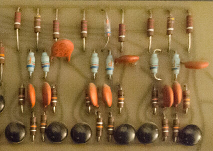
The three multivibrators used for column selection.
The multivibrators divide the master clock pulse by two, three separate times. This translates into 3 bits of binary logic, making for a digital translation of an analog controls interface. At the time, this was very groundbreaking.

The pulser/clock section of the 132. The original reference oscillator was much simpler, but probably unstable
The most staggering idea about this digital/analog control system is the whole process all happens at break-neck speed. The recipe is extremely risky; a supersonic clock, low tolerance parts, and a fully discrete circuit. Timing errors aplenty. On multiple occasions, the prototype we made would lock up the entire system due to tolerance factors. Careful amounts of tuning and time and error were sacrificed to stabilize the 132 to the point where it became structurally sound. From the original photos of the 132 circuit board, one can tell that Don was at wits end trying to improve it, as the kludges and tacked on resistors seem almost rushed and frenetic in their placement.
THE ROAD TO THE 132

The first “block diagram” labeling of the 132. The wiring was the worst.
In the early days of the project, we had written off the 132 as a module that we would never see. It seemed unobtainable and without any input or responses from Mills, whether informal or formal, the quest was in limbo. Onto the back burner it went. Much to Chip’s dismay, I would pull out the photos of the circuit board that existed on the internet and spent countless hours trying to modify the image in Photoshop to see the traces through the substrate, a tactic that had worked for the 192. The photo posted by Joel at Waveformless was practically useless with Instagram filters and its low resolution, but I kept at it.
One of the aspects of the project that remains behind the curtain are the many iterations of designs we go through before we reach a working prototype. The first trace that I had ever attempted was a 155, and I was so inexperienced at that point, that I keep a photo of it to remind myself how much the project has grown. Yeah, wait until the 155 page for that travesty. Eventually, we got bored with the information we had on other modules, and Chip and I both pooled all of our efforts into deciphering the 132 as it became more attainable a goal.
R&D (OR, HOW I LEARNED TO QUIT WORRYING AND BEAT MY HEAD AGAINST A WALL)
The first tracing attempt was not half bad. I would stare at photos for a while, and scribble down some preliminary traces based on what I could see, and what I would estimate as connections based on the relationships between the components. For example, the multivibrators are mostly estimations here, they later needed corrections.
By the time we did receive a photo of the board, we had already completed our build, and the only adjustments we needed to make were for more period accuracy.

First trace that we would eventually start seeing in our sleep.
The first real issue was getting the pulser to fire. One would think that this would be an easy task, but this absorbed so much of our free time, hilarity ensued. We fed the pulser circuit into MultiSIM to test it before we populated a second board. The first board did not do too well.

The night we tried to power up the first iteration of the 132. Not an email you want to receive.
This is a good place to talk about tolerances, because we had to make minor adjustments to the resistors around the core, just to get clean pulses timed properly. The idea was to get the capacitors in the multivibrator to charge in a linear fashion, so we needed to see equally timed rising edges to this segment. Big surprise, we weren’t so lucky. But we did manage to get seismograph readings from the San Andreas Fault Line.

This is not a pulser in peak form, no matter what the internet memes tell you.

Once we figured out some tweaks to the components, we FINALLY got a clean and concise pulser, firing happily away. Now that we had the green light to populate a second board, we chomped at the bit and flew through the build. Sadly, the pulser was the only thing that worked beautifully— we hooked up the rest of the circuit to discover that we had a nice white noise generator. The 132 became a paperweight— a placeholder in Chip’s demo case to remind us that sometimes we should leave well enough alone.
Frustrated, we reached out to Dave Brown at Modular Synthesis to offer assistance, who offered some expert advice on how the module worked along with some insight, but we still could not get it to cycle through the 32 steps.
IT’S ALIVE!!
This story remains one of the high points in M.E.M.S. history, because the 132 finally did get fixed, the very first time that Chip and I worked together under one roof. Backstory is in order, in case you haven’t seen the bio page— Chip lives in Detroit, and I live in Buffalo. Up until this point in the story, our research had already transpired for a year— long distance.

Tensions running high
The first school that we were to visit was Wesleyan University, to decipher and inspect the rare 113 Touch Controlled Voltage Source and 120 Voltage Controlled Distributor. Aside from this research, we had offered to speak at Ron Kuivila’s Compositions Symposium to explain to the students what the project was all about. One idea that Chip had explored at University of Michigan was bringing a demo system to teach the students patch basics on. We brought the 132 to show off, paperweight or not. It was an interesting piece regardless, and perhaps an epiphany would occur between Michigan and Connecticut that would breathe life into it.
While Chip drove to my home base to meet up, I studied the drawing and the photo of the circuit board as closely as possible and finally found what would be the needle in the haystack of errors. We missed a trace! When Chip arrived, we rushed into the basement workshop, soldered one piece of buss wire across, and the rest is history.

I hate pixels
ENOUGH ALREADY, WHAT DOES IT SOUND LIKE?
I’ve waxed poetic about this module enough, and descriptions are for the forums to argue over. Here is a video of the 132 Waveform Synthesizer in full glory, with a 2H9 for effects.
For those of you who follow the addictive and informative Source of Uncertainty podcast hosted by Kyle and Robert, there is a full episode dedicated to showcasing the 132 and the project. This can be found HERE along with multiple episodes that are well worth a listen.