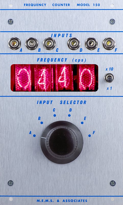
FREQUENCY COUNTER MODEL 150

What a steal… $5?
This will more than likely be short and sweet, as there’s not much to say about a Frequency Counter. But what a piece of equipment!
Four nixie tubes display the frequency of up to 16 selectable inputs, 6 from the front panel, and the other 10 from a rear connector, possibly meant to connect to a 124 Patch Bay.
This would have been an invaluable module for tuning oscillators and filters.
NIXIE TUBES

Exploded view of a nixie tube, with breakdown of how the cathodes stack,
Nixie tubes are brilliant in their design, and were beautiful indicators. The tubes were brought to the public in 1955 by Burroughs, who penned the tube the NIX 1 (Numeric Indicator eXperimental No. 1). Nixies completely changed the world in terms of creating visual interfaces for electronics. Now equipment could display alphanumeric data that could be read quickly and efficiently. Many early test equipment specimens in the late 50s all the way through the 70s utilized these displays in lab tools, or anywhere you needed a reading. Frequency Counters, Voltmeters, Ohmmeters, and many more.
The cathode numbers inside the tube are illuminated when they are energized, so a series of decade counters are sending signals to the tube driver circuit, to change the numbers in a linear fashion as the frequency changes.
WE’RE GONNA NEED A BIGGER BOAT

First person to ask about module depth and if it will fit in their case wins a prize.
The 150 is not actually Don’s complete design, more than likely it was a one-off commission for what was to be Owsley Stanley’s red paneled system. Instead of designing a TTL logic based frequency counter from scratch, Don opted to hack apart a HP Frequency Counter and repurpose it for the module. It would have been interesting to see if this module introduced any noise when being placed near other audio modules, since the voltage needed to illuminate a nixie is close to 300V. Most frequency counters of this era are also 5-6 digits, so the circuit board was sawed off to remove the first digit in the megahertz range, since it would not be needed.
How do we know this was an HP counter? Telltale signs. Gold plated contacts, trace patterns on the edge card, and HP was one of the few around this time using nixies with upside down digits.
The x1/x10 toggle switch turns on a decimal position at the third tube to switch between significant figures.

Detail of an HP 5221B Nixie driver and logic board, slightly different from the one in the 150 but utilizing the same mounting method.
150 REPLICATION

M.E.M.S. 150, with nixie daughter card.
The 150 is complete. Great strides have been made in terms of slimming down and cleaning up the power supply for a new frequency counter module that plays well with the rest of the system. To do this, we designed a TTL logic based counter circuit from the ground up. For power requirements, the new 150 will be able to take advantage of the multiple options available today for powering and driving nixie tubes, thanks to the hobbyist community surrounding nixie related clocks and other projects. The module will run on +15V which will then be converted to the proper high voltage rail for the tubes themselves.
The nixie display board is perpendicular to the mainboard, held in place with a heavy duty edge card socket so it is at the perfect viewing position at the window of the module.