
PROGRAMMABLE PULSER MODEL 242

242 Panel, CBS Musical Instruments. Photo is courtesy of Tom Rowlands.
The Buchla paradigm houses an incredible source of event based triggers. One of the most flexible modules in terms of timing pulses, the 140 Timing Pulse Generator is a prime example of foreshadowing. The flexibility of the alternating pulses can really add to a patch, either with syncopation or lockstepping.
In addition to the alternating pulses, and pulse period adjustment, the user can create up to three pre-programmed pulse rhythms (A, B, and C). Using the pin matrix, you even get a visual representation of the program. A row of LEDs sweeps by to indicate the step progress. These were 2mm Monsanto LEDs, which also made an appearance on the 217 Multiple Touch Controlled Voltage Source. Additionally, the top row of pins (labeled “n”) sets the number of steps. Unfortunately this also sets the length of all three “programs”.
The Programmable Pulser was initially included in the CBS Electronic Music System #3, alongside the 410 Module Cluster, 216 Touch Controlled Voltage Source, and the 258 Dual Oscillator.
Chris Whitten performing on the Electronic Music System #3

The original matrix was made by Sealectro, similar to the matrices found in many EMS synthesizers.
PIN MATRIX REPLICATION
The first hurdle we had with the 242 was pretty obvious. The matrix. Matrices were once excellent ways to eliminate large control panels. They had been used for years in telecommunications and industrial applications. Even large scale lighting operations were programmed this way, the lights in Piccadilly Circus were once programmed with large banks of pin matrices.
Since getting originals from Sealectro was impossible, and Ghielmetti custom matrices are cost prohibitive, we decided to make our own using a suggestion from Dave Brown - a sandwich of PCBs, using passthrough headers. This was a perfect solution - since the matrix specified in the Buchla did not use diode pins.
Because we were using headers set to a specific pitch, we had to change the size of the matrix. Pins were made from buss wire with 3D printed pin grips.

Exploded view of the three boards that make up the pin matrix. Photos from Dave Brown’s build.
Below is a couple scans of the artwork and matrix sheets designed for the 242. It is interesting to note on the right side of the schematic that the line widths are specifically called out.


There were two revisions of the 242, to eliminate a kluge/mistakes on the first layout. These PCBs are owned by Gregory Kramer. We were able to discern the changes and utilize this as the “242A”, even though the layout does not label it as such. We decided to label our boards 242A as to avoid confusion for the two layouts we had traced.


Dave Brown’s personal build, he opted for different switches instead of the expensive Dialco ones.


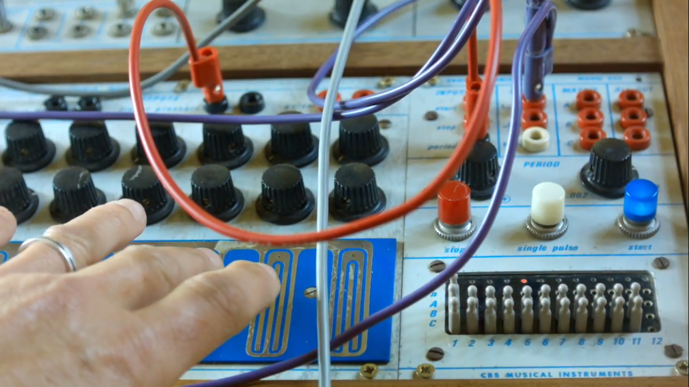
242 OPERATION
Our version of the 242 works beautifully, and the first few times we patched it, we became hyper-aware of it’s tendency to become the “brain” of the patch. Using the pin matrix allows us to quickly facilitate rhythmic changes in the system on the fly.